Dimensioning Sheet Metal Parts Solidworks

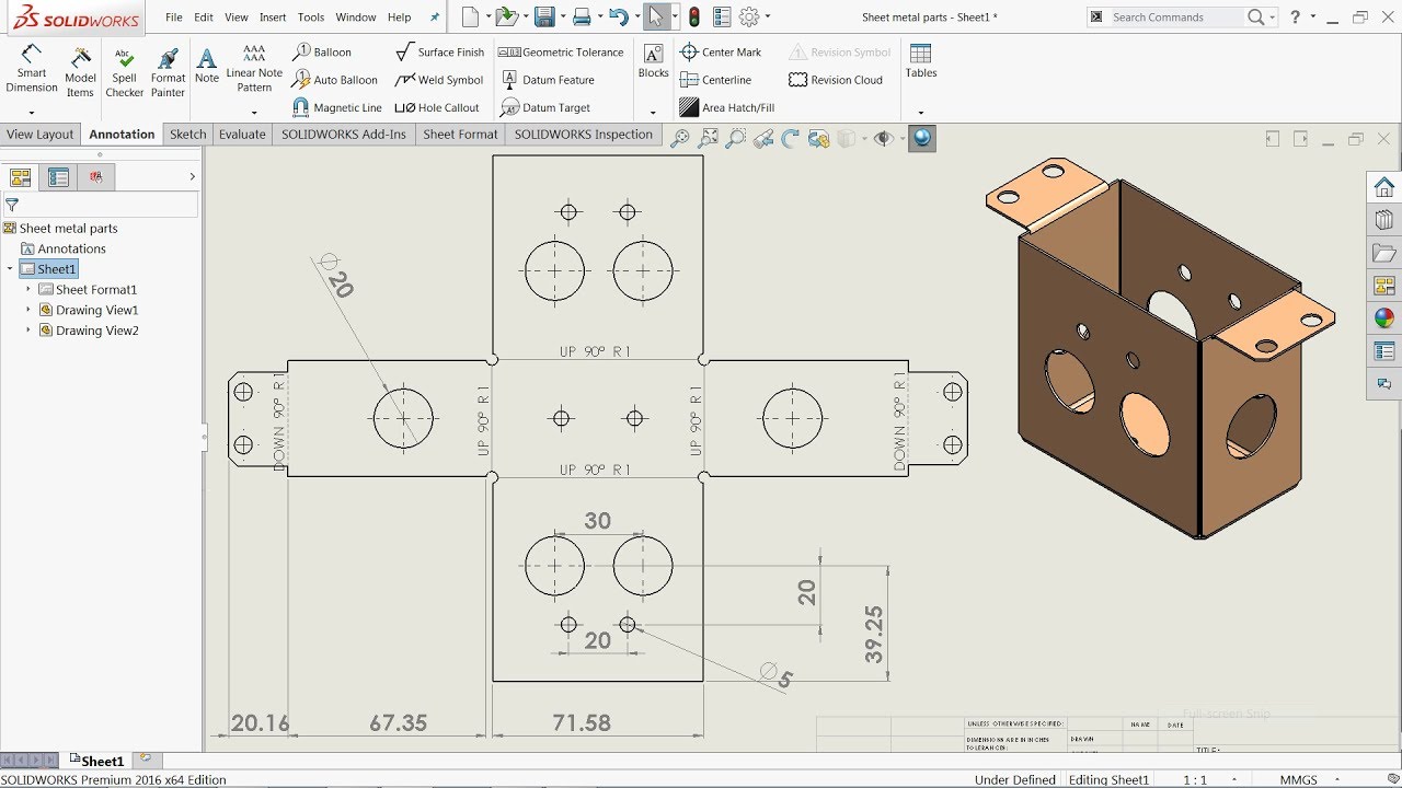
Solidworks Sheet Metal Drawing Tutorial Bend Line Flat Pattern Unfolded Bend Table Punch Table Youtube
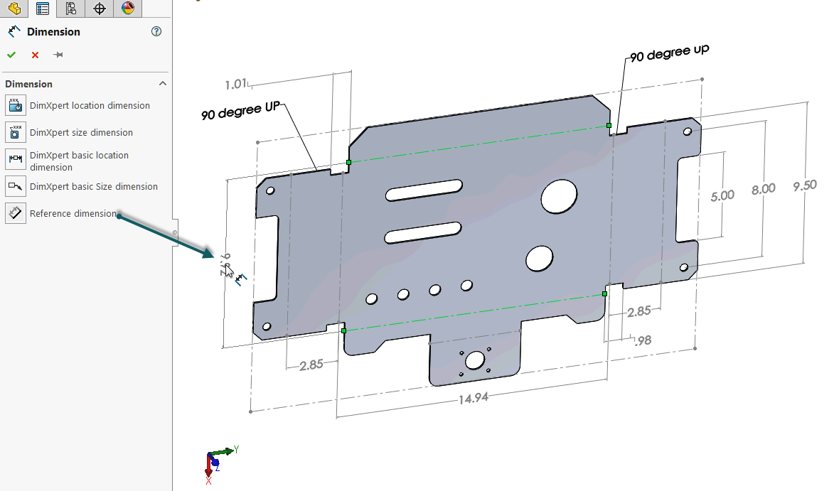
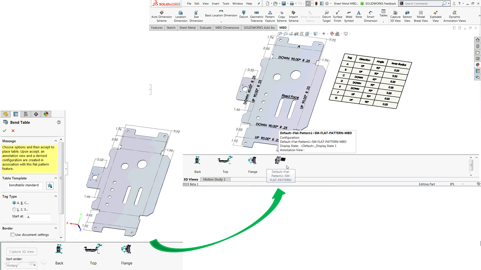
How To Define The Mbd Data Of Sheet Metal Parts Engineers Rule
Solidworks Tutorial Sheet Metal Cone Youtube

Solidworks Sheet Metal Drawings Youtube
2012 Solidworks Help Creating Drawings Of Sheet Metal Parts
How To Dimension The Undimensionable Solidworks Drawing Computer Aided Technology

The sheet metal tool allows you to quickly create sheet metal part designs using a simple design process all helping to save time and development costs.
Dimensioning sheet metal parts solidworks.

What Happened To My Flat Pattern View Computer Aided Technology

Solidworks Sheet Metal Gauge Table And Properties Youtube

Using Solidworks Sheet Metal Functionality Create A B Size Drawing Sheet Metal Drawing Technical Drawing Mechanical Engineering Design

20 Latest Bending Drawing Sheet Metal

Using Ordinate Dimensions
2018 Solidworks Help Using Polar Dimension Schemes For Geometrically Toleranced Parts

Sheet Metal Drawing Sheet Sheet Metal Sheet Metal Drawing Drawing Sheet

Solidworks 2015 Bend Lines Youtube

Pmi Enhancements In Solidworks Mbd 2016 Engineers Rule

Solidworks Adding Drawing Annotations To Notes Youtube
2018 Solidworks Help Datum Feature Symbols

Solidworks Sheet Metal Tutorial Panel Youtube Sheet Metal Sheet Metal Drawing Sheet Metal Work

Here Is A Quick Solidworks Sheet Metal Tutorial The Sheet Metal Tool Allows You To Quickly Create Sheet Metal Part D Solidworks Tutorial Solidworks Sheet Metal
How To Make Solidworks Drawings In 5 Minutes Solopoint Solutions Inc
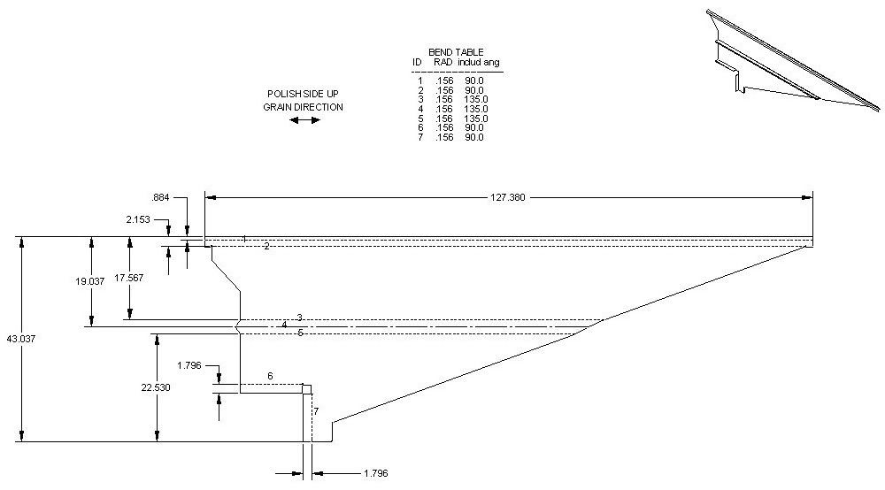
Sheet Metal Dimensioning Standards

Here Is A Quick Solidworks Sheet Metal Tutorial The Sheet Metal Tool Allows You To Quickly Create Sheet Metal Part D Solidworks Tutorial Solidworks Sheet Metal
Mysolidworks Official Solidworks Community

Solidworks Update Standard Views Youtube
Https Encrypted Tbn0 Gstatic Com Images Q Tbn 3aand9gcsftkzqgtggsbgs5vksvlmj5nx5ovb560qcfwk2uwxdpjil9xvk Usqp Cau
2017 Solidworks Help Autodimension A Drawing

The Fastest Way To Add Smart Dimensions In Solidworks

Autodesk Inventor Sheet Metal Tutorial Basics Youtube Autodesk Inventor Metal Furniture Design Solidworks Tutorial

How To Label Solidworks Coordinate Points In A Drawing View
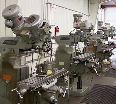
Practical Machinist Largest Manufacturing Technology Forum On The Web
Source : pinterest.com
